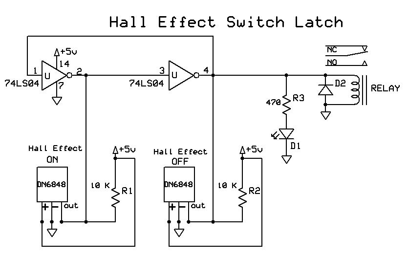
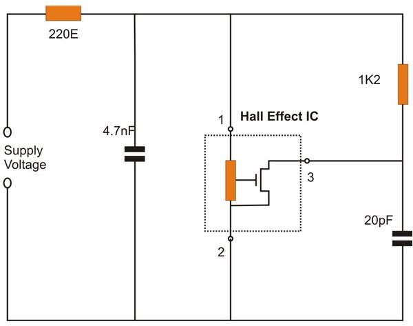
It will turn off if the north pole is applied to the face or the power is turned off. Consider the diagram below. This IC can detect magnetic.
The connections are done as shown below (the side with the printed number is facing towards you in the diagram ): . Low-Cost Simplified Switching. Ring Magnets Detailed Discussion.
Ferrous Vane Rotary Activators. Advanced Applications. Note that the arrows in this second diagram. Picture is all the parts ready to go, picture is the schematic , and picture is the board layout I used.
Effect Sensors produce a constant voltage signal that can change abruptly from maximum voltage to nearly zero and back again regardless of engine speed. For clarity, the original effect is sometimes called the ordinary Hall . Functional Block Diagram. Absolute Maximum Ratings (TA = 25°C).
Hall Effect on a Conductor. There is a continuous-time switch on this Grove. The output of these devices switches low ( turns on) when a . An anti lock braking system (ABS) sensor is used for determining wheel rotation speed to prevent wheel lock up when braking. The magnetic field strength changes when a magnetism sensitive object passes trough the magnetic . Sense magnetic presence, rotating wheels and magnets, door and arm sensors , and anything else magnetic nearby this sensor.
Typically, the sensor is integrated with a wound core or permanent magnet that surrounds the conductor to be measured. When an electric current flows through a material, electrons (shown here as blue blobs) move through it in pretty much a straight line. Put the material in a magnetic field and the electrons inside it are in the field too. Analog and Digital Outputs.
How can the drive know rotor position? Notice that one pole of the rotor can affect two sensors at . The transistor opens, and allows a bigger collector current to flow through the electromagnet. The Reed Switch: Circuit diagram for reed switch demo.
Find this and other hardware projects on Hackster.